D66-16- manual adjuster
D66-16- manual adjuster
- Product details
- Product parameters
Product description:
A promise to adjust illustrates, belongs to the automotive parts, gear disk set in the middle of the first shaft hole, side set a convex sets, positioning convex on both sides of the sliding groove is formed between Taiwan and the first limit edge: tooth plate in the middle of the second shaft hole, a gear ring on one side of the wall, yu-jong middle cavity, for the bottom of the cavity finite slice vessel: small tooth board has four, its lateral teeth, the inside of the first and second bottom, side a second limit on the edge;The driving mechanism includes the camshaft, which has a shaft hole, a spring groove on the outer wall and a camshaft seat on one end, and a CAM block on the camshaft seat.In the middle of the limit film, there is a camshaft seat, and the cavity wall is limited.The closed ring is enveloped in the tooth plate and the teeth;The spring is located on the camshaft outside the disc seat;The shaft sleeve has a cylinder, and the center of the cylinder has a shaft sleeve and a sleeve cap at one end.High strength, small clearance and small volume, easy to unlock and assemble, precise machining accuracy and low cost.
3D renderings:

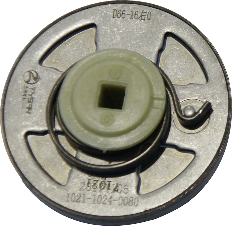
Introduction to product structure:
The scope of its air travel is 94 °, toothed part 86 °, adjustment precision of 2 °
1. The structure of the electric modulator.
2. The inner diameter of the plastic shaft in the middle of the core piece is about 7.2(+0.10 ~ 0).
3, if use double illustrates, illustrates its active side to unlock or shaft is connected to the connecting rod in the form of welding. Connecting rod size for each 7.2 (0 ~ 0.05), and then to nylon sleeve as a limit, illustrates from active test of wear to the driven side illustrates, driven side illustrates the cone shell closed.
4. If a single regulator is used, the same axis or unlocking plate of the same active side is welded with the connecting rod, and the other end is welded with a gasket and the connecting rod, thus closing the Y direction.As shown in figure
5、D66-16 design of the lower plate.
(1) design of disc spring inner bracket and lower connecting plate
2) the split part of the plate spring inner bracket and the lower connecting plate, and the coil spring is installed on the inside of the upper connecting plate.
6. D66 manual adjustment welding requirements: in the welding process, the inner circle needs to be protected to prevent spatter.
Melt the plastic core shaft and spatter to jam the return spring or enter the core to affect the function of the toner.Protective cover material requirements: bronze.
7. Welding method and appearance.
A, the yellow area is shown as the welding area (the coil spring is outside the toner assembly)
B. The yellow area is shown as the welding area (the coil spring is in the inner structure of the adjuster assembly)
8. Welding positioning
The regulator USES two convex points and the middle square hole positioning, and the other four points are used to avoid.
9. Board welding.
D66-16 manual retractor welding requirements: in the welding process, the inner ring area needs to be protected to prevent the splattering of the plastic core shaft and splashing into the core of the regulator, thus causing the failure of the function.
Specific to back side plate welding, hope to weld the back side plate with metal cover to cover the area.
10. Welding method and appearance.
In order to prevent excessive welding heat radiation, a series of functional problems are caused by the thermal deformation of the parts.Use the graphic method to weld.
11. Welding parameters
Recommended welding parameters
Welding method: CO2 gas shielded welding.
Diameter of wire: 1.0mm.
Welding current: 130~150A.
Welding voltage: 17~19V.
Air flow: 15~18L/min.
Dry extension length :10mm.
Welding speed: 7~10mm/s.